

Post by Running Bear on Oct 12, 2008 17:14:04 GMT -5
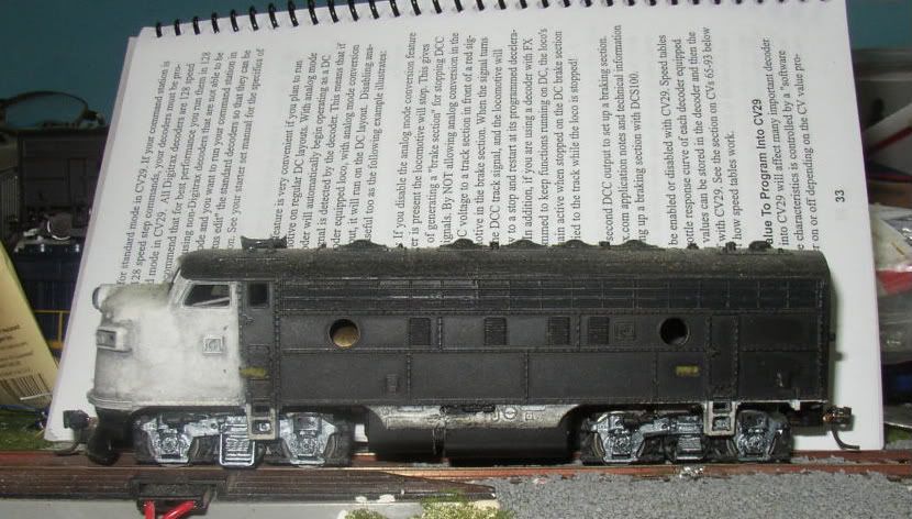
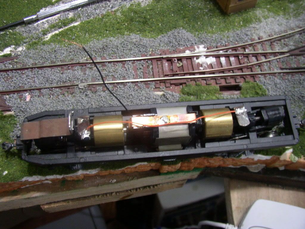
Here's the loco I'll be converting. Ignore the Mantua body shell. It has nothing to do with the conversion except to cover the chassis.
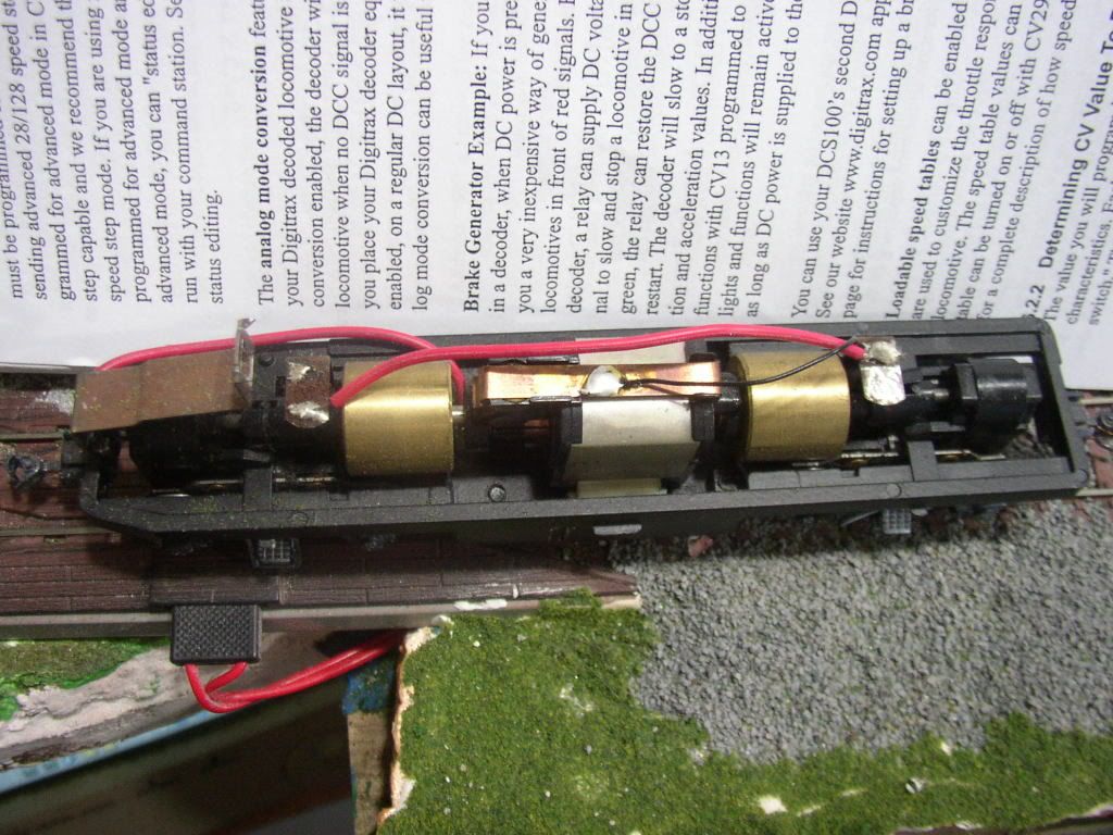
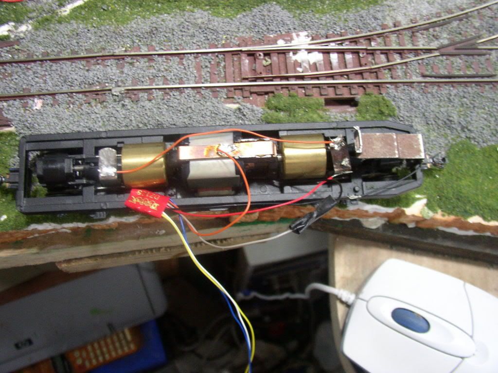
We can see that this loco was converted early in it's history for superior pickup. The contact from the motor to the trucks was removed and flexible wire put in it's place.
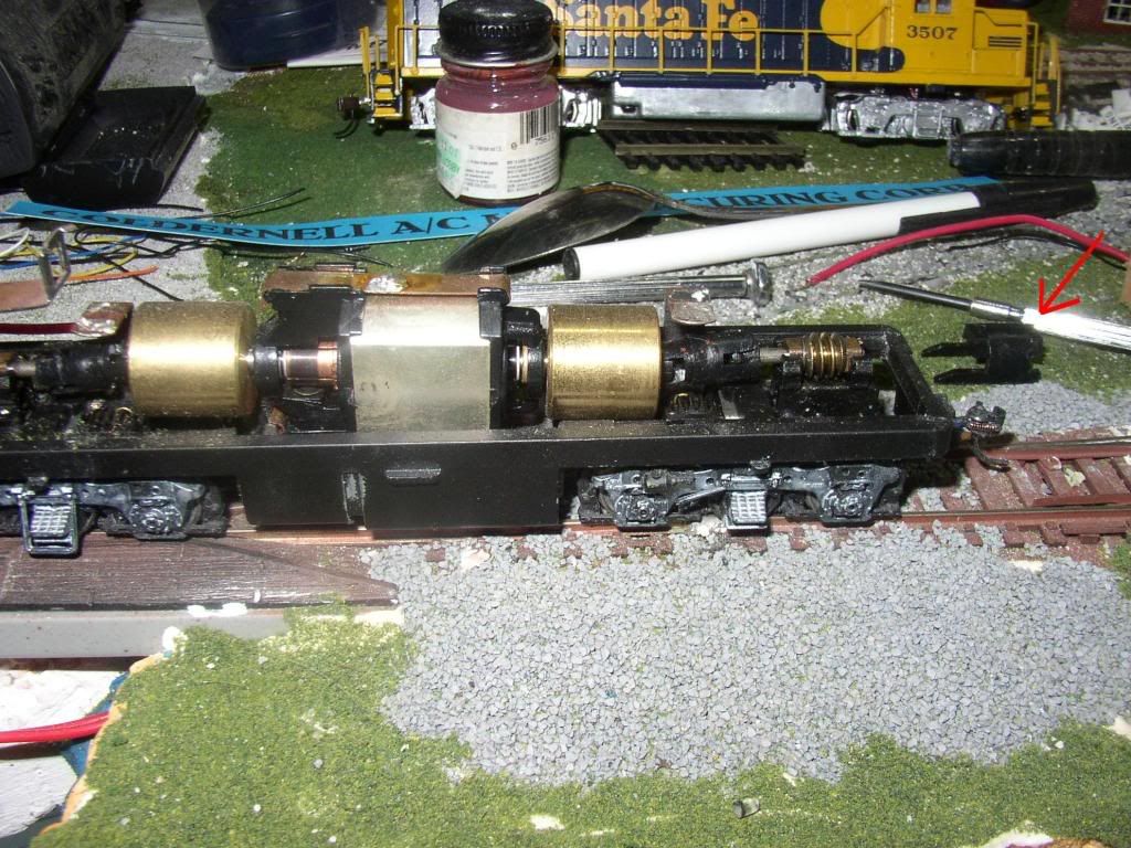
Now that I've removed the wire I can also remove the worm housings from the tops of the truck ... The arrow points to one of the housings.
Now I carefully remove the worm assemblies and set them aside. The trucks will now fall free of the chassis. I set them aside. Now I gently pull up on one side of the motor so that it pulls one of the motor mounts free and comes out of the frame. Since this loco was converted for superior pickup it has a wire soldered to the bottom strip of the motor. Normally there would be two metal prongs here and I would simply break them off. I then put a strip of electrical tape in the bottom of the well the motor was in. This is to prevent any future contact between the motor and the frame. I remove the wire from the motor and solder a thinner wire (same gauge as what's on the decoder) in it's place.
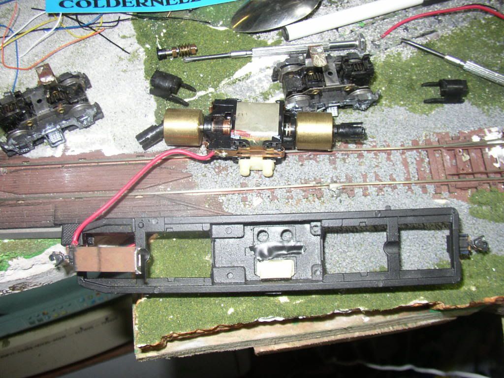
I then reassemble the chassis making sure the wire on the bottom of the motor doesn't get pinched anywhere. I also added a jumper wire between the pickup clips of the front and rear trucks.
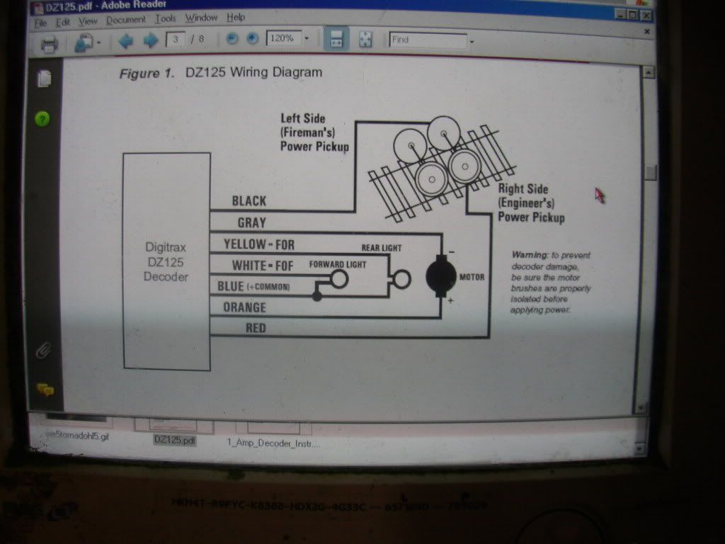
This is the wiring diagram for the 2 function decoder I will be installing. This diagram is generic to all the NMRA compliant decoders I have used.
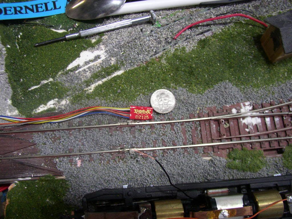
Here's the star of the show shown next to a dime to give you a good idea of it's size. This is a Digitrax DZ125 decoder (Z Scale). This decoder is robust enough to operate in most HO Scale equipment and is small enough to use where space is at a premium.
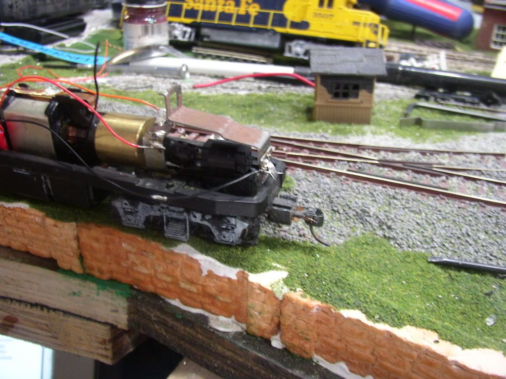
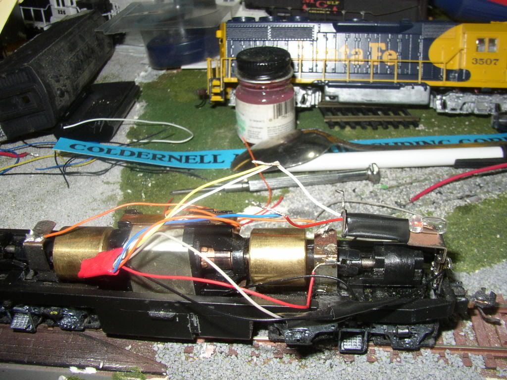
Here I have soldered the decoders black wire (left rail pickup) to the locos frame. The red wire (right rail pickup) has been solder to front trucks top pickup clip.
Now I solder the decoders gray wire (motor - contact) the black wire I soldered to the bottom of the motor earlier. The decoders orange wire (motor + contact) to the clip on top of the motor.
I'm using a 12 volt 25mA mini lamp (Radio Shack #272-1141) in this install. This means I will not be using any resistors. I set the bulb in place on the locos headlight clip and secure it with a piece of electrical tape. I then solder the white and yellow wires of the decoder to the bulbs white wire and then solder the decoders blue wire to the bulbs red wire.
I then insulate all exposed connections with electrical tape then secure the decoders wires to the top of the motor with a strip of electrical tape, making sure that the decoder itself is clear of the motor. This way it won't be picking up heat from the motor.
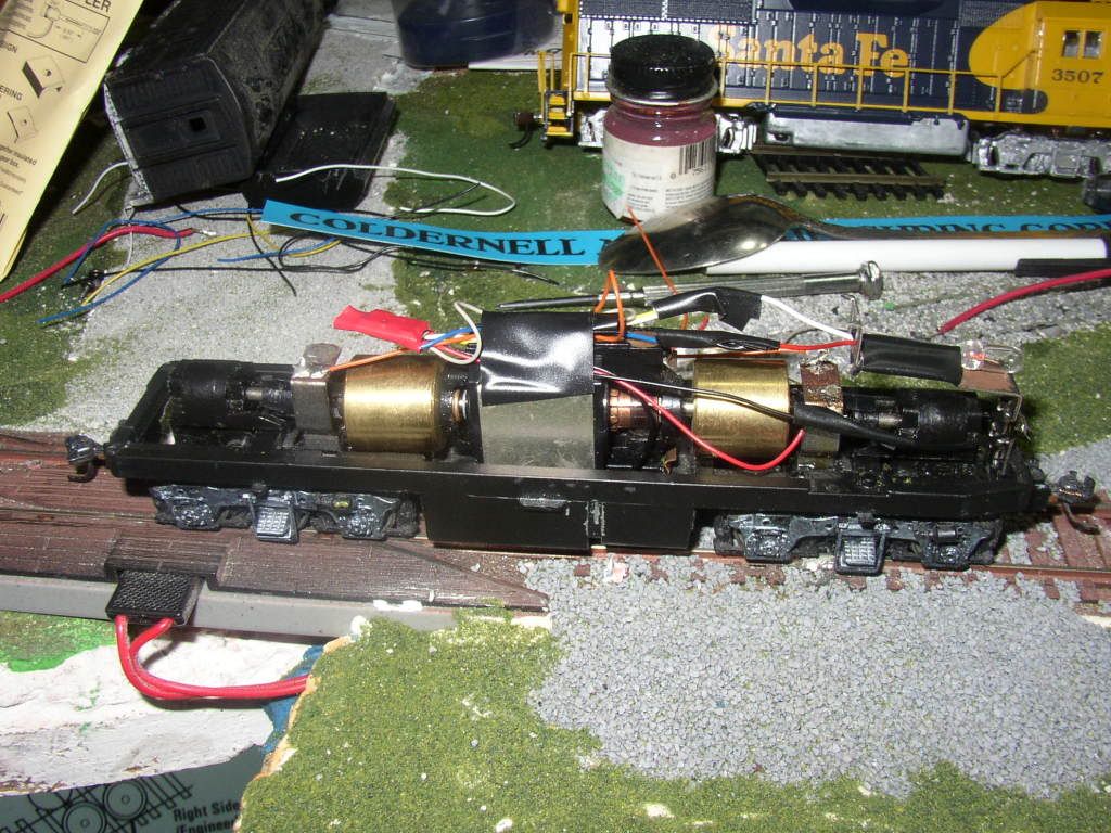
I will now use my Digitrax DCS50 to program the decoder with whatever settings I want it to have.
We can see that this loco was converted early in it's history for superior pickup. The contact from the motor to the trucks was removed and flexible wire put in it's place.
Now that I've removed the wire I can also remove the worm housings from the tops of the truck ... The arrow points to one of the housings.
Now I carefully remove the worm assemblies and set them aside. The trucks will now fall free of the chassis. I set them aside. Now I gently pull up on one side of the motor so that it pulls one of the motor mounts free and comes out of the frame. Since this loco was converted for superior pickup it has a wire soldered to the bottom strip of the motor. Normally there would be two metal prongs here and I would simply break them off. I then put a strip of electrical tape in the bottom of the well the motor was in. This is to prevent any future contact between the motor and the frame. I remove the wire from the motor and solder a thinner wire (same gauge as what's on the decoder) in it's place.
I then reassemble the chassis making sure the wire on the bottom of the motor doesn't get pinched anywhere. I also added a jumper wire between the pickup clips of the front and rear trucks.
This is the wiring diagram for the 2 function decoder I will be installing. This diagram is generic to all the NMRA compliant decoders I have used.
Here's the star of the show shown next to a dime to give you a good idea of it's size. This is a Digitrax DZ125 decoder (Z Scale). This decoder is robust enough to operate in most HO Scale equipment and is small enough to use where space is at a premium.
Here I have soldered the decoders black wire (left rail pickup) to the locos frame. The red wire (right rail pickup) has been solder to front trucks top pickup clip.
Now I solder the decoders gray wire (motor - contact) the black wire I soldered to the bottom of the motor earlier. The decoders orange wire (motor + contact) to the clip on top of the motor.
I'm using a 12 volt 25mA mini lamp (Radio Shack #272-1141) in this install. This means I will not be using any resistors. I set the bulb in place on the locos headlight clip and secure it with a piece of electrical tape. I then solder the white and yellow wires of the decoder to the bulbs white wire and then solder the decoders blue wire to the bulbs red wire.
I then insulate all exposed connections with electrical tape then secure the decoders wires to the top of the motor with a strip of electrical tape, making sure that the decoder itself is clear of the motor. This way it won't be picking up heat from the motor.
I will now use my Digitrax DCS50 to program the decoder with whatever settings I want it to have.


 My Gallery=
